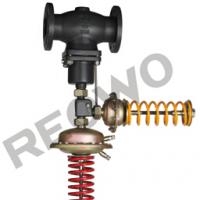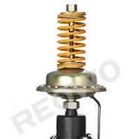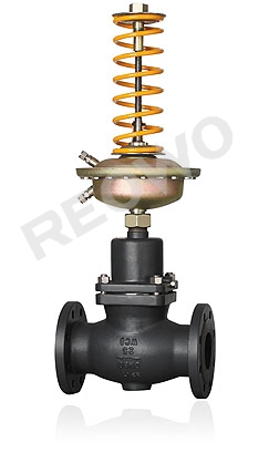

The 30D03Y/30D03R self-operated differential pressure control
Phone: +86 18939876995
Fax: +86 86-52805855
Mobile: +86 86-52805855
The 30D03Y/30D03R self-operated differential pressure control
Summary
The30D03Y/30D03Rself-operated differential pressure control valve is composed of the control valve ,actuator and a spring used for pressure setting。It is suitable for controling differential pressure in the pipes of non-corrosive liquids, gases and steams. when the valve is closed
The main features are as follows:
1.It has the pressure balancing function with high sensitivity.
2.Low noise, reliable performance, free of maintenance
3.The standard modular design is adopted.
4.Various combined controls can be carried out through the assemblies.
Body
|
DN |
15、20、25、32、40、50、65、80、100、125、150、200、250mm |
|
|
PN |
Class150、300 |
|
|
Flange standard |
ANSI、JIS、DIN GB JB(special standards can be offered according to user requirements) |
|
|
Body material |
WCB、CF8、CF3、CF8M、CF3M |
|
|
Plug material |
Hard seal |
Stainless steel (304、316、316L) |
|
Soft seal |
Stainless steel embedded with rubber ring |
|
|
Pressure balancing |
Stainless steel bellows (DN15~125), balanced diaphragm (DN150~250) |
|
Actuator
|
Effective area (cm2) |
80 |
250 |
630 |
|
Pressure setting range |
0.1~0.6 0.05~0.3 |
0.015~0.15 0.01~0.07 |
0.005~0.035 |
|
Minimum differential pressure that ensures normal work of the pressure valve |
≥0.04 |
≥0.01 |
≥0.005 |
|
Allowable maximum differential pressure between the upper a nd lower diaphragm chambers |
1.25 |
0.4 |
0.15 |
|
Material |
Diaphragm cover: galvanized steel sheet; Diaphragm: EPDM or FKM with fiber |
||
|
Control pipeline connection |
Copper pipe or steel pipe Φ10X 1(mm); Ferrule connection: R1/4" |
||
Note: ※The pressure setting range corresponding to the effective area does not apply to valves with DN150-250.
Performance
|
Set value error |
±8% |
|||
|
Allowable leakage (under stipulated testing conditions) |
Hard seal |
4×0.01% valve rated capacity |
||
|
Soft seal |
DN15~50 |
DN65-DN125 |
DN150~250 |
|
|
10 bubbles/ min |
20 bubbles/min |
40 bubbles/min |
||

|
1Body |
2Seat |
3 Valve shaft |
4 Bonnet |
5 Diaphragm cover |
6 Diaphragm |
|
7 Spring |
8 Adjusting nut |
9 Bellows |
10Balanced diaphragm |
11Charging valve |
|
Allowable working temperature
|
DN |
15~125mm |
150~250mm |
|
|
seal type |
Hard seal |
≤150℃ |
≤140℃ |
|
Cooling tank≤200℃ |
Cooling tank and extension ≤200℃ |
||
|
Cooling tan k and heat sink ≤350℃※ |
Cooling tank and extension ≤300℃※ |
||
|
Soft seal |
≤150℃ |
||
Note: ※It indicates the allowable working temperature is valid only when the medium is steam
and the body with PN40 shall be adopted w hen the temperature resistance is 350℃.
Rated flow coefficient, noise measuring coefficient, allowable differential pressure
|
DN |
15 |
20 |
25 |
32 |
40 |
50 |
65 |
80 |
100 |
125 |
150 |
200 |
250 |
|
|
Rated flow coefficient |
4 |
6.3 |
8 |
16 |
20 |
32 |
50 |
80 |
125 |
160 |
280 |
320 |
450 |
|
|
Noise measuring coefficient Z value |
0.6 |
0.6 |
0.6 |
0.55 |
0.55 |
0.5 |
0.5 |
0.45 |
0.4 |
0.35 |
0.3 |
0.2 |
0.2 |
|
|
Allowable differential |
PN16 |
1.6 |
1.5 |
1.2 |
1 |
|||||||||
|
pressure (Mpa) |
PN40 |
2 |
||||||||||||
Working principle
After throttling by the plug and seat, the before-valve pressure P1 of the process medium is changed into the after-valve pressure P2. Through the control pipeline, P1 is input to the upper diaphragm chamber of the actuator and acts on the top disc.
The acting force produced balances the reacting force of the spring, determining relative positions of the plug and seat and controlling the before-valve pressure. W hen the before-valve pressure P1 increases, the acting force of P1 that acts on the top disc will increase accordingly.
At the time, the acting force on the top disc is higher than the reacting force of the spring to make the plug move away from the seat, until the acting force on the top disc balances the reacting force of the spring. At the time, the flow area between the plug and seat is increased, the flow resistance becomes lower and P1 is reduced to the set value. Likewise, when the before-valve pressure P1 decreases, the acting direction is reverse to the above. This is the working principle during the control of before-valve pressure.
When it is necessary to change the set value of before-valve pressure P1, please adjust the adjusting nut.

I. Dimensions and weight of control valve
|
DN (mm) |
15 |
20 |
25 |
32 |
40 |
50 |
65 |
80 |
100 |
125 |
150 |
200 |
250 |
|
L (mm) |
130 |
150 |
160 |
180 |
200 |
230 |
290 |
310 |
350 |
400 |
480 |
600 |
730 |
|
B (mm) |
212 |
212 |
238 |
238 |
240 |
240 |
275 |
275 |
380 |
380 |
326 |
354 |
404 |
|
Weight (Kg) |
6.2 |
6.7 |
9.7 |
13 |
14 |
17 |
29 |
33 |
60 |
70 |
80 |
140 |
220 |
|
B1(mm) |
— |
— |
— |
— |
— |
— |
— |
— |
— |
— |
630 |
855 |
1205 |
|
Weigh(Kg) |
— |
— |
— |
— |
— |
— |
— |
— |
— |
— |
140 |
210 |
300 |

II. Dimensions and weight of actuator
|
Effective area (cm ) |
32 |
80 |
250 |
630 |
|
R (mm) |
172 |
172 |
263 |
380 |
|
H (mm) |
435 |
430 |
470 |
520 |
|
Weight(Kg) |
7.5 |
7.5 |
13 |
28 |

Fax: +86 86-52805855
Mobile: +86 86-52805855


